Components - Antennas Research Ltd

Antennas Research


Antennas Research Ltd. 2024
WebRadio
Antenna components designed for manufacture - case studies.
1. Waveguide.
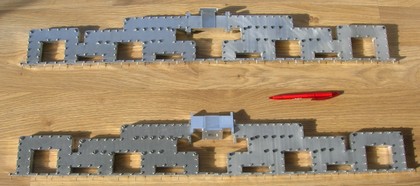
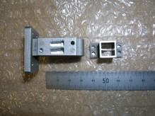
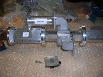
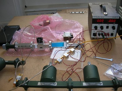
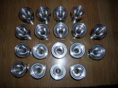
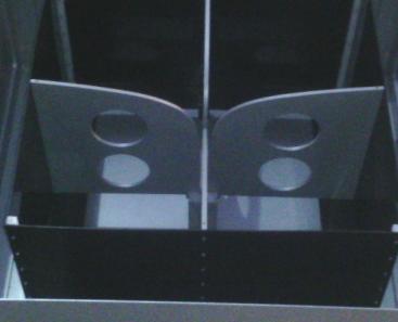
Below are photos of a 10-way waveguide power divider, developed by us for a radar product. In common with the microstrip power divider illustrated in the radar section, this item sets the amplitude taper across an antenna aperture so as to reduce sidelobes.The waveguide output ports will each be connected to a microstrip circuit on a multi-layer printed circuit board. Ten such PCBs form a phased array radar antenna aperture of 80cm x 60cm.
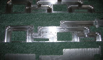
internal view of components
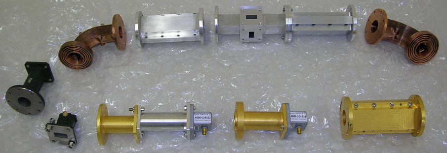
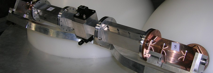
external view of assembled waveguides
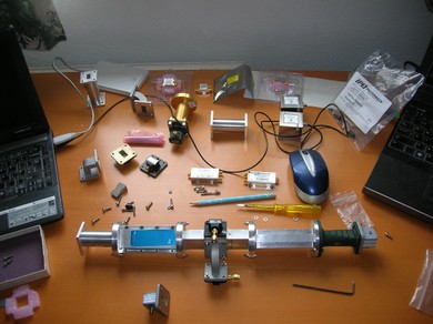
We have built up an extensive CAD library of waveguide parts, many of which have been manufactured for use in antenna related products.
Components we can design and supply include:
- primary feeds
- tee junctions ('magic' tees) with internal matching vanes
- 'rat race' hybrids
- filters
- bends
- iris polarisers and septum polarisers
- rectangular-to-rectangular and rectangular-to-circular transitions
- quad-ridged horns
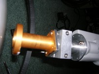
Experiments with monopulse ports on Ku band feed chain
A set of x-band primary feeds we designed and built recently
2. Lens antennas
Lens antennas can make interesting alternatives to reflector antennas. I have developed several types. In once case, a very low sidelobe antenna was required which had dissimlar beamwidths in the two principal planes - around 5º and 9º. When projected onto the ground from a point in space (e.g. an airship or a low earth orbit satellite), and at an oblique angle, this beam produces a circular footprint for a millimetre-wave micro-cell.
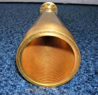
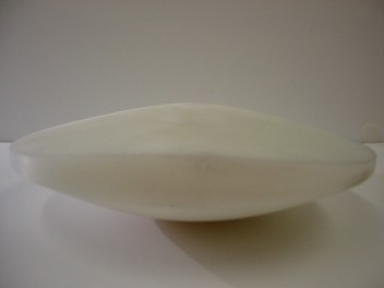
A Corrugated horn for 30 GHz An asymmetric lens for shaped beam
The lens was shaped to achieve the required two different beamwidths. It was machined from a low cost polymer billet. (You'll see that white plastic is not very photogenic !) You could try this with a reflector antenna too, but would probably struggle to illuminate it with a well behaved primary feed which would need to sit in front of the reflector aperture. With the lens the reverse applies and so the feed does not get in the way. On these topics I contributed a chapter to this text book published in 2013:

3. Quad ridged horns.
The dual-ridged horn principle allows very wide bandwidth operation and is a niche type sometimes encountered in electromagnetic compatibility (EMC) applications, and electronic listening. A quad-ridged horn supports dual-linear polarisation but is much more difficult to design ! An example is shown below.
I was tasked with exploring the limits of input impedance match versus the antenna’s dimensions. At the bottom end of the frequency range, the antenna is electrically small. As a consequence, it tends to reflect rather than radiate incident RF energy. This is the classical problem of small antennas (like the type in your phone handset or key fob) and at the time it was a new design challenge for me.
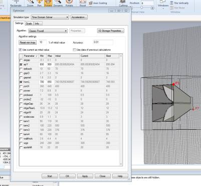
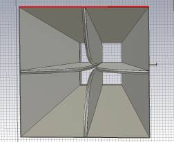
optimizer window CAD modelTaking this starting point, I experimented with different horn lengths, widths, and ridge flare parameters until the specification could be met while still mounting the antenna in its intended host vehicle. The final design was quite novel and only slightly resembled the example shown. Sometimes, lack of familiarity with established principles allows one to approach a problem with an open mind, and so arrive at an unusual solution.
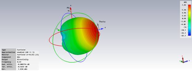
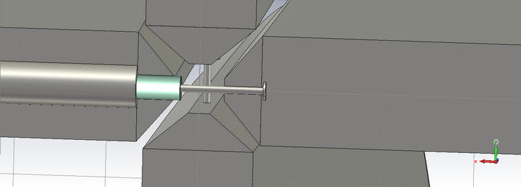
Quad ridged horn, typical radiation patternFeed region.The feed region is also very critical. Here, a coaxial cable spans opposite ridges. The ridge chamfer, cable dimensions and location along the z-axis, and the proximity of the back short (waveguide end) all have an influence, which of course changes with frequency. Everything interacts with everything else. The two polarisations each have a dedicated cable feed, but these of course cannot be exactly co-located.
coaxial probes in feed region
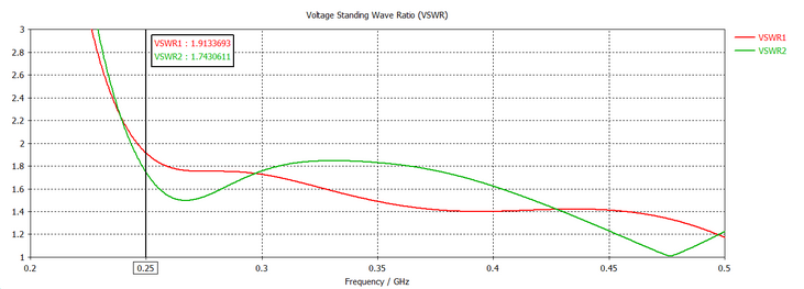
Following this electrical design exercise, I was asked to produce mechanical models which would allow the client to manufacture a prototype according to a set of drawings. Later, measurements of both input match and radiation patterns confirmed the validity of the design.Simulated VSWR
The fabricated quad ridged horn.
The above horn was developed for a UHF airborne radar. I can adapt the design to most other radio frequencies and bandwidths. Here's a link to simulation results for another horn for 5-18 GHz (it's from my old site).
4. Sector Antennas for Millimetre Wave Applications, 38-40 GHz.
The lens antenna has excellent characteristics for this application:
- High gain, > 20 dBi
- Beam shaping /null filling.
- Simplicity of construction.
- Ease of scalability to other frequencies e.g. 28 GHz
- Scalability to other beamwidths / sector coverage angle.
- Waveguide feed port.
- Compact and very rugged.
- Low cost.
Null filled antenna: radiation patterns